Overview
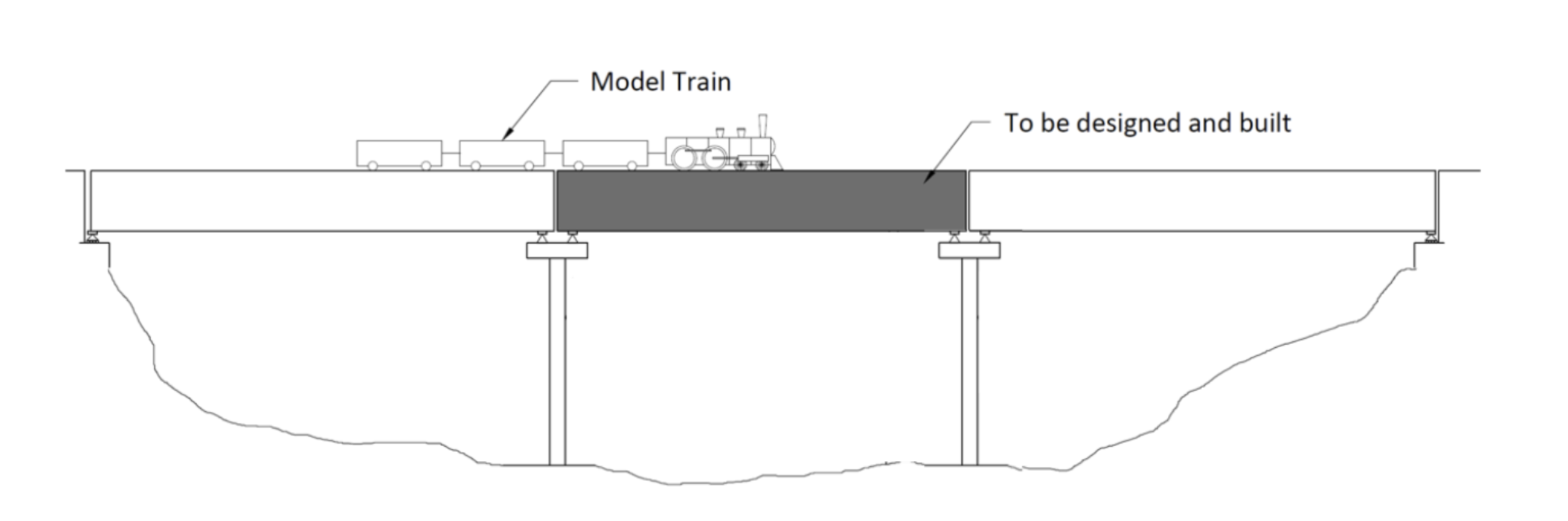
The Challenge: Design and build a matboard beam bridge spanning 1200 mm capable of supporting the maximum possible moving train load while minimizing total bridge mass — a direct strength-to-weight optimization problem under material and geometric constraints.
My Role: Working in a team of three first-year engineering science students at University of Toronto, I co-developed the MATLAB inductive prototype that generated bending moment and shear force envelopes used to drive every cross-section design iteration. I also contributed to physical construction and led post-failure analysis of the structural discrepancy between simulation and physical testing.
The Outcome: Our MATLAB model enabled systematic convergence from a baseline FOS of 0.84 to a final design FOS of 2.38 — a 2.83× improvement in structural safety. The subsequent physical bridge failure at 133 N (vs. 1092 N predicted) produced the project's most important engineering insight: verification under real manufacturing constraints is non-negotiable.
Process & Methodology
Decomposing the Design Space with Attribute Listing
Rather than approaching the bridge as a monolithic design decision, we decomposed the cross-section into independent structural variables: flange width, web height, glue tab size, and matboard layer thickness. This allowed us to adjust one parameter at a time during each MATLAB iteration and observe the directional effect on factor of safety — preventing the team from abandoning good geometries because a single variable was underperforming.
This systematic decomposition was a departure from treating the bridge as a single holistic shape — and it is directly transferable to any design space where variables interact non-linearly.
MATLAB Inductive Mathematical Prototyping
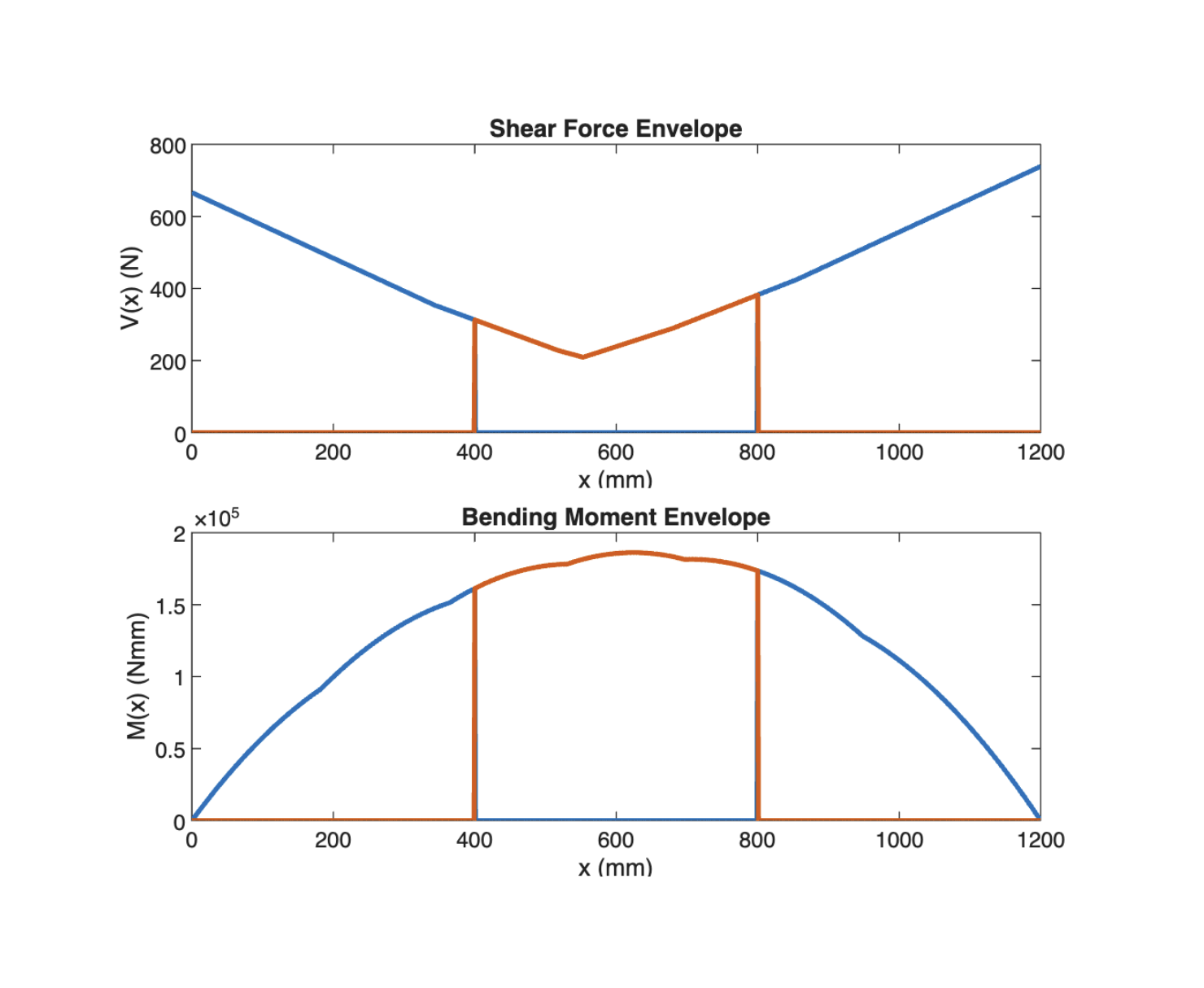
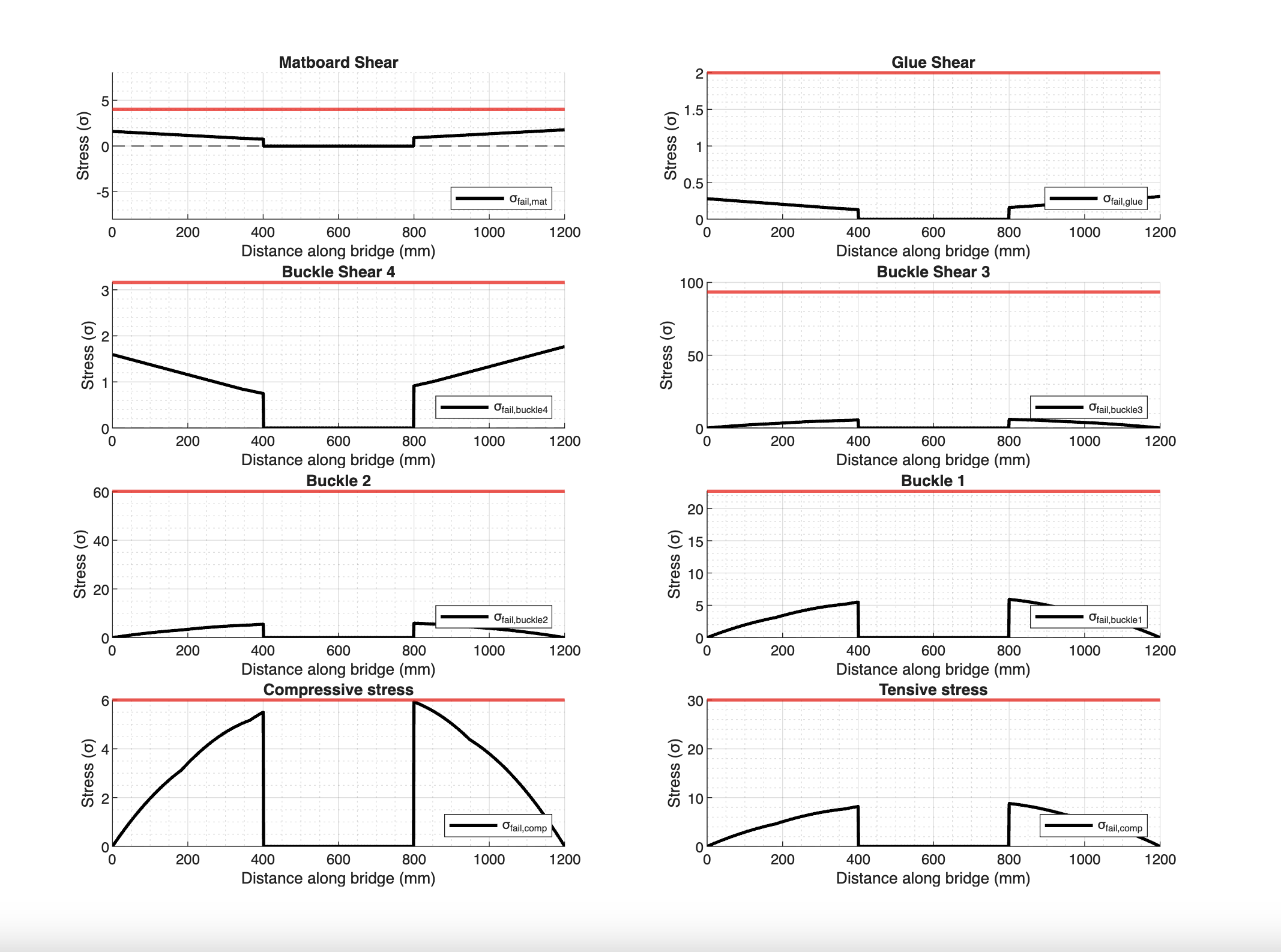
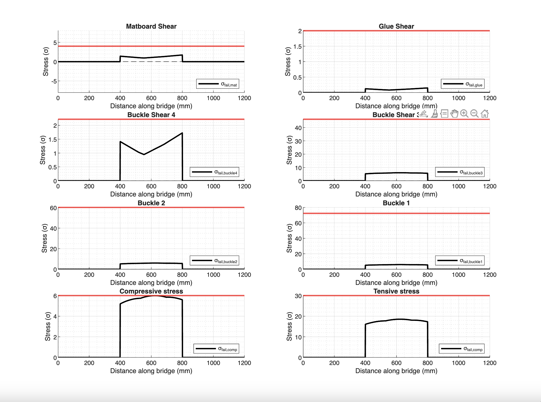
My team and I coded a MATLAB structural model that generated Bending Moment and Shear Force Envelopes across the full 1200 mm span under the moving train load case. The model evaluated failure predictions across six modes:
- Compression (top flange)
- Tension (bottom)
- Shear (matboard web)
- Shear (glue joints)
- Flexural buckling (Case 1, 2, and 3)
- Shear buckling
For each cross-section concept generated during diverging, the model output a full FOS profile. By observing which failure mode was limiting the design at each iteration, we could identify exactly which variable to adjust next — making the convergence systematic rather than intuitive.
FOS progression:
| Iteration | Critical Failure Mode | Overall FOS |
|---|---|---|
| Baseline design | Case 1 buckling | 0.840 |
| After web height optimization | Compression | 2.38 |
Cross-Section Architecture
Our final design uses three distinct cross-sectional zones across the 1200 mm span, each engineered for the dominant internal force at that location:
Middle cross-section: Extended web height to resist the peak bending moment at mid-span. Longer webs increase second moment of area (I), directly reducing extreme fiber bending stress.
End cross-sections: Added both top and bottom flanges to resist the peak shear force near the supports. Flanges increase shear flow capacity at the locations where the shear force envelope peaks.
This zoned architecture — rather than a uniform cross-section — was the key insight that allowed simultaneous optimization for both bending and shear without adding unnecessary material mass.
Physical Construction and Failure Analysis
Our physical bridge failed at 133 N against a predicted 1092 N — a discrepancy of 87.8%. Post-failure analysis identified the primary cause: splice joints in the web and flange introduced by the limited matboard sheet length (insufficient to cover the full 1200 mm span in a single piece).
The MATLAB model assumed perfectly continuous, homogeneous material. The splices created stress concentration points not present in the simulation. Glue joint inconsistency from manual application introduced further variability.
Failure location: The spliced section of the web, as predicted by the observed crack pattern during testing.
Key insight: A mathematically optimized design is only as strong as its weakest unconsidered variable. Real-world manufacturing constraints — material dimensions, joint quality, construction tolerances — are themselves engineering variables that must be modeled, not assumed away.
Results
- Factor of safety improvement: 0.84 → 2.38 (2.83× increase) through MATLAB-guided iteration
- Failure load predicted: 1092 N
- Failure load measured: 133 N — discrepancy traced to splice geometry and glue joint variance
- Physical failure mode: Web splice delamination under combined shear and bending
Lessons Learned
Simulation and reality diverge at the construction boundary. The MATLAB model was accurate for ideal geometry. The failure was not a modeling error — it was a manufacturing constraint that was never incorporated into the model. Every simulation has a set of assumptions; listing those assumptions explicitly is as important as the model itself.
Optimization requires decomposition. Treating the bridge as a collection of independent variables — rather than a single design — allowed targeted, efficient iteration. Each MATLAB run answered a specific question. This is the foundation of any systematic optimization workflow.
Verification is not confirmation — it is challenge. I entered physical testing expecting to validate our simulation. The result instead revealed an entire class of failure modes our model had not considered. I now treat physical testing as the stage most likely to find what you did not think to model.
View PDFs
Engineering Design Portfolio - view report of this project and others (PDF)